Vision Pipeline
They say a picture is worth a thousand words...
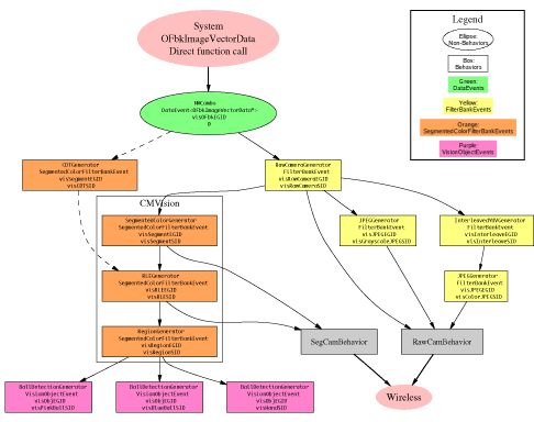
(click for an enlarged image map)
Overview
Tekkotsu's vision system is divided into many separate modules. Each module communicates by throwing events to the EventRouter, which then sends an event to any dependent modules.
Data is typically stored in filter banks. Each filter bank contains images in several resolution layers, forming an image pyramid. In addition, each filter bank can contain multiple channels, such as Y, U, and V color information.
The image computations are lazy evaluated. The FilterBankEvents and SegmentedColorFilterBankEvents which are thrown do not contain the actual image data - they reference the generator itself, and the data does not need to be computed until it's actually accessed. Once computed, the image data is cached so future accesses are cheap, until the generator receives notice its own source has new image data available, which invalidates the cache.
The section marked "CMVision" on the diagram are the modules which use the CMVision library. The CMVision modules are somewhat intertwined due to the nature of their data structure layouts. The intermixed data fields allow some short cuts, but the tradeoff is that to replace one of these sections you may need to need to know a bit about what the downstream components are expecting.
It is important to keep in mind that the AIBO's system provides several image channels, each at several resolutions, and this pipeline will allow you access the results of pulling any of these images through the pipeline to any stage.Information Flow
The following information is for the default layout.
However, all the setup is done in <project>/StartupBehavior_VisionSetup.cc,
so you can actually disconnect/reconnect everything as you see fit, or
even add new stages.
Data is sent from the system to the Main process. This data is organized by 3 data layers, each of which represents a different resolution level. In addition, there are currently 7 data channels available from the system, which store:
- Y - intensity (brightness information)
- U - reddish color channel
- V - bluish color channel
- Y horizontal derivative - hilights vertical edges
- Y vertical derivative - hilights horizontal edges
- Y horiz. & vert. derivative - hilights diagonal edges
- CDT - Color Detection Table - segmented (indexed) color channel
The symbolic names for these channels are defined in channel_id_t
of RawCameraGenerator.
The main process simply wraps a data event around a pointer to
the OFbkImageVectorData structure that it is given by the system.
This is received by the RawCameraGenerator
and CDTGenerator.
The CDTGenerator
will
pull out the CDT channel from the system
structure and fill out a SegmentedColorFilterBankEvent for it.
Note
that by default the CDTGenerator isn't connected to anything, and
further, to use
it you will need to call the appropriate system functions to define
the color region thresholds. Some modification of the
CDTGenerator
may be necessary for full functionality - this is just starter
code.
By default, CMVision is used for segmentation. The CDT
segmentation is faster since it is done in hardware, but it is less
flexible than CMVision because its color regions must be rectangular,
which usually leads to less accurate segmentation.
The RawCameraGenerator parses the system structure and fills
out a FilterBankEvent. By default, the RawCameraGenerator also
adds a few more resolution levels than is directly available from the
system:
- 5 - double resolution - for the Y channel, this is computed
by combining the 4 Y channels to reclaim the full resolution of the
camera. For the other channels, it simply upsamples the
pixels. All of this requires some significant processing, so use
it sparingly.
- 4 - full resolution - direct from system
- 3 - half resolution - direct from system
- 2 - quarter resolution - direct from system
- 1 - eigth resolution - references every other pixel of
quarter resolution image
- 0 - sixteenth resolution - references the every fourth
pixel of quarter resolution image
You can use the symbolic names defined in ProjectInterface.h
to access
these, but since they go in numerical order, it would also make sense
to just use the numerical values listed above.
Note that you must use the increment value given by the getIncrement() function to
properly access the bottom two layers. All other layers will have
an increment value of 1.
From the RawCameraGenerator the image information goes down several different paths.
One is through the CMVision library, which will segment the
color image into an indexed image, then run length encode it, and
then connect runs into regions. Some noise removal is performed
during RLE compression to achieve better compression as well as cleaner
segmentation.
Each of these steps is thrown as a separate event so you can
access the intermediate data. For instance, you may be able to do
further processing or detection directly on the RLE compressed image
instead of the segmented image itself, which could save some data
processing. Alternatively, other algorithms may be better off
accessing the uncompressed image if they do not run through all the
pixels in order. The key here is to use whichever information
best suits your algorithm, because it's all available.
The main use of the JPEG compressed image is to be streamed over wireless ethernet to a desktop computer for viewing. However, it is conceivable that some algorithms may be able to directly run off of the data produced by the JPEG compression. For example, a type of edge detection, image summary, or gradient information could be obtained quickly from the compressed image.
Transmission over the network is handled by the RawCamBehavior and SegCamBehavior. The RawCam will select a resolution layer and channel from either the raw image data or one of the JPEG compressors depending on current settings. The SegCam will pick from the original segmented image or the RLE compressed version depending on current settings. (These settings are defined in the <project>/ms/config/tekkotsu.cfg file, and can be changed at runtime with the !set command (see FAQ entry))
Object detection is currently handled by a BallDetectionGenerator, which receives the region information and attempts to find square-ish regions which have the same area as a circle would if it were contained in the region's bounding box.
Usage
Since the image data is lazily evaluated, there is very little
overhead if your behavior subscribes to image data but never actually
calls the getImage()
function to get the image data.
However, if your behavior is subscribed to one of the detectors, it will force the detector to access the image information on each frame to perform detection so the detector can decide if it should throw an event. Thus, you should always be sure to unsubscribe from object detectors whenever you no longer need them to reduce computational load. If just one behavior is causing the image information to be accessed, the whole pipeline from that generator to the root will have to be evaluated. However, any further accesses by other behaviors will have trivial overhead.
Also, you should try to have each of your behaviors access the same resolution layer. Since each layer is handled separately, accessing a layer which has not been computed will cause the entire pipeline to be run for that layer. (It might be an interesting bit research for someone to write a method of cost minimization that will decide when it's better to resample results from an already available layer instead of recomputing the requested layer from scratch. It's not always obvious when to do one or the other, although some additional smarts could be hardwired if you find yourself needing two different layers.)
The functions available from the FilterBankEvent give all the
information necessary for interpreting image pixels, supporting a
variety of memory layouts. By using the values given in
the event appropriately, you can ensure your code will be able to
handle
image data, even if upstream components change their data layout, such
as interleaving pixels instead of rows, or putting each channel in a
contiguous memory block. (Currently, the system interleaves rows
from each channel within a large memory block, but most of the Tekkotsu
FilterBankGenerators will store each channel in a separate memory
block.)
In order to receive image information, you simply need to call
addListener() on the
EventRouter, just like for any other information source. Then
cast the EventBase you receive to the appropriate type, and call getImage() and other functions
as needed.
The generator IDs are used to designate the format of the data
returned by getImage(). For instance, if you get an event from visRLEEGID, it's going to be an
array of CMVision run
structures. But if it's from visRawCameraEGID, it's just a
straight pixel array.
The source IDs are used to differentiate multiple generators
which might produce the same data types. For instance, the
CDTGenerator and CMVision SegmentedColorGenerator both produce visSegmentEGID events.
However they will have different source IDs so they can both be active
at the same time and behaviors can choose one or the other.
Another example is the JPEG compressors - one source is grayscale
individual channels, the other is a color image in only the first
channel.
Thus, if you want to make a new image source, all you need to
do is start throwing events from a different source ID. You don't
have to turn off or break the other sources to add your own.
For further reading, the Dutch ARchitecture Project for Aibos
(DARPA) has written a nice tutorial on adding custom vision processing
code which can be found here: visionInDepth.pdf